Lab 007 Understand Address Resolution Protocol (ARP)
Watch Full Demo on YouTube:
Lab Objective:
The main objective of this lab is to gain practical experience in verifying Address Resolution Protocol (ARP) operations within a network environment.
Through this exercise, we aim to understand how ARP facilitates the mapping of IP addresses to MAC addresses, enabling devices
to communicate effectively on the same local network segment. Additionally, we seek to explore the dynamic nature of ARP cache entries and troubleshoot any issues related to ARP resolution.
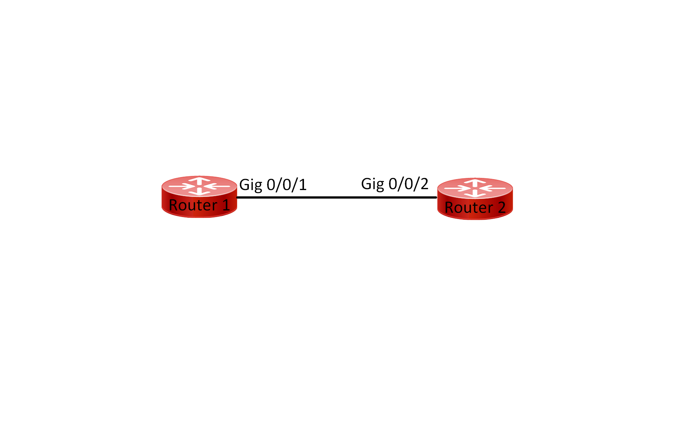
Lab Topology:

Equipment Required:
- 2x Cisco Router
- 1 x Cisco Switch
- Console Cable
- Ethernet Cable
- Computer with Terminal emulation software e.g. PuTTY
IPv4 Address Table:
| Device Name | Interface ID | IPv4 Address | Subnet-Mask |
| Router 1 | GigabitEthernet0/0/0 | 172.16.0.1 | 255.255.255.252 |
| Router 1 | GigabitEthernet0/0/1 | 172.16.0.130 | 255.255.255.128 |
| Router 2 | GigabitEthernet0/0/0 | 172.16.0.2 | 255.255.255.252 |
| Device Name | Interface ID | IPv4 Address | Subnet-Mask | Default Gateway |
| PC1 | Fa0 | 172.16.0.131 | 255.255.255.128 | 172.16.0.130 |
| PC2 | Fa0 | 172.16.0.131 | 255.255.255.128 | 172.16.0.130 |
List of Command Summary:
| Command | Command Description |
| enable | enters privileged EXEC mode. |
| configure terminal | enters global configuration mode from privileged EXEC mode. |
| hostname [hostname] | Assign a device name to router. |
| interface [type number] | Change from global configuration mode to interface configuration mode. |
| description [interface description] | command is used in Cisco IOS to add a description to a specific interface. This description is a text string that can help network administrators identify and understand the purpose or function of the interface. It does not affect the operation of the interface itself but can be useful for documentation and troubleshooting purposes. |
| show arp | displays the ARP cache table. |
| arp -a | show the ARP cache entries on a Windows PC. |
| arp -n | shows the ARP cache entries on a Linux PC. |
| ipconfig /all | used in Windows operating systems to display detailed information about all network interfaces and their configurations |
| show mac-address-table | displays the MAC (Media Access Control) address table, also known as the MAC address forwarding table or CAM (Content Addressable Memory) table. This table contains information about the MAC addresses learned by the switch, along with the corresponding VLAN information and interface association. This command is mainly used on Cisco Switches. |
| no shutdown | enables an interface. |
| show running-config | save the running configuration to the startup-configuration file. |
| end | exit configuration mode. |
| exit | exits one level in the menu structure command. |
Lab Task:
- Connect the devices according to the provided topology.
- Connect to the CLI of the routers and enable privileged EXEC mode and go to configuration mode. Configure the appropriate hostname on each device as per topology shown above.
- Enable both interfaces (GigabitEthernet0/0/0-1) on Router1 and enable interface GigabitEthernet0/0/0 on Router2. Please include link description to specify where the device is connected to.
- Display the ARP table. Observe the output, do you see any IP and MAC address mapping? why?
- Configure IPv4 addresses on Router 1, Router 2, PC 1, and PC 2 interfaces. Configure the gateway for each PC. Please refer back to the IPv4 address table mentioned above.
- Verify that each interface is in the up/up state and check the MAC address for each interface on Router1, Router2 and PC1.
- View the ARP table on each Router using the appropriate command.
- Verify connectivity between the devices using the ping command.
- Now try again and view the ARP table on each Router, what do you observe?
- From Switch1 look at the CAM table and observe the MAC address.
- Disconnect the ethernet cable from PC1 and connect it to PC2 and observe how the ARP cache changes.
- Initiate a ping from PC2 to the default gateway.
- View the ARP table on Router1 once more, and observe the output.
- Shutdown the fastethernet0/1 interface on the switch, and then examine the ARP table. How long it would take for the ARP entry associated with the PC to be removed?
- Enable the fastethernet0/1 interface and make sure that connectivity is restored between PC2 and the gateway.
- Save the configuration across all network devices once everything is working.
Configuration Steps:
1. Connect Lab Devices: Connect the devices according to the provided topology
2. Change the name of both routers switches according to the topology:
On Router 1:
Router> enable
Router# configure terminal
Router(config)# hostname Router1
On Router 2:
Router> enable
Router# configure terminal
Router(config)# hostname Router2
On Switch1:
Switch> enable
Switch# configure terminal
Switch(config)#hostname Switch1
3. Enable both interfaces on Router1 and configure link description:
Router1:
Router1(config)#interface gigabitEthernet 0/0/0
Router1(config-if)#description “Link to Router2”
Router1(config-if)#no shut
Router1(config-if)#exit
Router1(config)#interface gigabitEthernet 0/0/1
Router1(config-if)#description “Link to Switch1”
Router1(config-if)#no sh
Router2:
Router2(config)#interface gigabitEthernet 0/0/0
Router2(config-if)#description “Link to Router1”
Router2(config-if)#no shut
4. When there are no IP addresses configured on the interfaces of a router or switch, the device cannot participate in IP-based communication, including Address Resolution Protocol (ARP). Since ARP is used to map IP addresses to MAC addresses, if the device does not have any IP addresses to resolve, there will be no ARP entries in the ARP table, and therefore no output from the “show arp” command
5. Configure ipv4 address on both routers:
Router1:
Router1(config)#interface gigabitEthernet 0/0/0
Router1(config-if)#ip address 172.16.0.1 255.255.255.252
Router1(config-if)#exit
Router1(config)#interface gigabitEthernet 0/0/1
Router1(config-if)#ip address 172.16.0.130 255.255.255.128
Router1(config-if)#exit
Router2:
Router2(config)#interface gigabitEthernet 0/0/0
Router2(config-if)#description “Link to Router1”
Router2(config-if)#ip address 172.16.0.2 255.255.255.252
Router2(config-if)#no shut
PC1:

PC2:

6. Verify each interface is up:
On Routr1: Interface GigabitEthernet0/0/0

On Routr1: Interface GigabitEthernet0/0/0:

On Router2: Interface GigabitEthernet0/0/0:

On PC1:

On PC2:

7. View the ARP table on each router:
On Router1:

On Router2:

Connectivity verification:
Ping from Router2 to Router1:
Router2#ping 172.16.0.1
Type escape sequence to abort.
Sending 5, 100-byte ICMP Echos to 172.16.0.1, timeout is 2 seconds:
.!!!!
Success rate is 80 percent (4/5), round-trip min/avg/max = 0/0/1 ms
Router2#
Ping from PC1 to Router1:
C:\>ping 172.16.0.130
Pinging 172.16.0.130 with 32 bytes of data:
Reply from 172.16.0.130: bytes=32 time<1ms TTL=255
Reply from 172.16.0.130: bytes=32 time=1ms TTL=255
Reply from 172.16.0.130: bytes=32 time<1ms TTL=255
Reply from 172.16.0.130: bytes=32 time<1ms TTL=255
Ping statistics for 172.16.0.130:
Packets: Sent = 4, Received = 4, Lost = 0 (0% loss),
Approximate round trip times in milli-seconds:
Minimum = 0ms, Maximum = 1ms, Average = 0ms C:\>
9. View the ARP table once more:

A router learns ARP entries through the ARP process, which is used to discover the MAC (Media Access Control) address associated with an IP address on the same network segment. You can see that this IP 172.16.0.131 is associated with this MAC address 0040.0B9D.8212 which is the physical address of PC1.
10. We issue the following command on the switch “show mac-address-table”:

The switch learned the MAC address of the PC, which is connected to port Fa0/1
11. Removed the cable from PC1 and plugged it into PC2 ethernet interface fa0:


12. We will initiate a ping to PC2’s gateway:

Now we will issue the “show mac-address-table” command on Switch1

You can see that Switch1 has learnt PC2’s MAC address and associated the MAC address with Fa0/1
13. You can see that Router1 has learnt the new MAC address and associated it with GigabitEthernet0/0/1 as shown below:

14. Follow the instruction below to shutdown FastEthernet0/1 on Switch1:
Switch1#configure terminal
Switch1(config)#interface fastEthernet 0/1
Switch1(config-if)#shutdown
By issuing the “show arp” command on Router1, you can see that the age of the arp entry for 172.16.0.131 is incrementing. It would take approx. 4Hrs for the ARP entry to remove the IP address from the ARP table. For more info see below:

To enable the interface on Switch1 Fa0/1 you can issue the “no shutdown” command:
Switch1#configure terminal
Switch1(config)#interface fastEthernet 0/1
Switch1(config-if)#no shutdown
%LINK-5-CHANGED: Interface FastEthernet0/1, changed state to up
%LINEPROTO-5-UPDOWN: Line protocol on Interface FastEthernet0/1,
changed state to up Switch1(config-if)#end


16. Save the configuration by issuing wr command
Note:
Address Resolution Protocol (ARP) is a critical networking protocol used to map IP addresses to MAC addresses within a local network. Here’s an in-depth explanation:
- Purpose: ARP resolves the layer 3 (network layer) IP address of a device to its corresponding layer 2 (data link layer) MAC address. This mapping is essential for data transmission between devices on the same local network segment.
- Operation: When a device needs to send data to another device on the same network, it checks its ARP cache (also known as ARP table) for the MAC address corresponding to the destination IP address. If the MAC address is not found in the cache, the device initiates an ARP request.
- ARP Request: The device broadcasts an ARP request packet containing the target IP address. The request is sent to all devices on the local network.
- ARP Reply: The device with the matching IP address responds with an ARP reply packet containing its MAC address. This reply is sent directly to the requesting device.
- ARP Cache: Upon receiving the ARP reply, the requesting device updates its ARP cache with the MAC address of the destination device. Subsequent communications to that IP address can now be sent directly to the MAC address stored in the ARP cache.
- ARP Timeout: ARP cache entries have a limited lifetime and expire after a certain period of inactivity. When a cached entry expires, the device may need to perform a new ARP request to update the MAC address mapping.
- ARP Table: Network devices maintain an ARP table, which is a database containing IP-to-MAC address mappings learned through ARP requests and replies. Administrators can view and manage ARP tables to troubleshoot connectivity issues and monitor network activity.
- Proxy ARP: In some cases, a device may respond to ARP requests on behalf of another device. This is known as proxy ARP and is used to facilitate communication between devices on different network segments.
Overall, ARP plays a fundamental role in enabling communication between devices within the same local network by dynamically resolving IP addresses to MAC addresses.
Conclusion:
In this lab, we learned how ARP functions to resolve IP addresses to MAC addresses in a local network environment. We observed how ARP cache entries are created and updated dynamically as devices communicate on the network.
This lab provides valuable hands-on experience with ARP and enhances understanding of fundamental networking concepts.
Packet Tracer Lab (Pre/Post configuration):
Download the file below and open the word document to access the Packet Tracer labs.


