Lab 004 Configure and Verify IPv6 Static addresses
Watch Full Demo on YouTube:
Lab Objective:
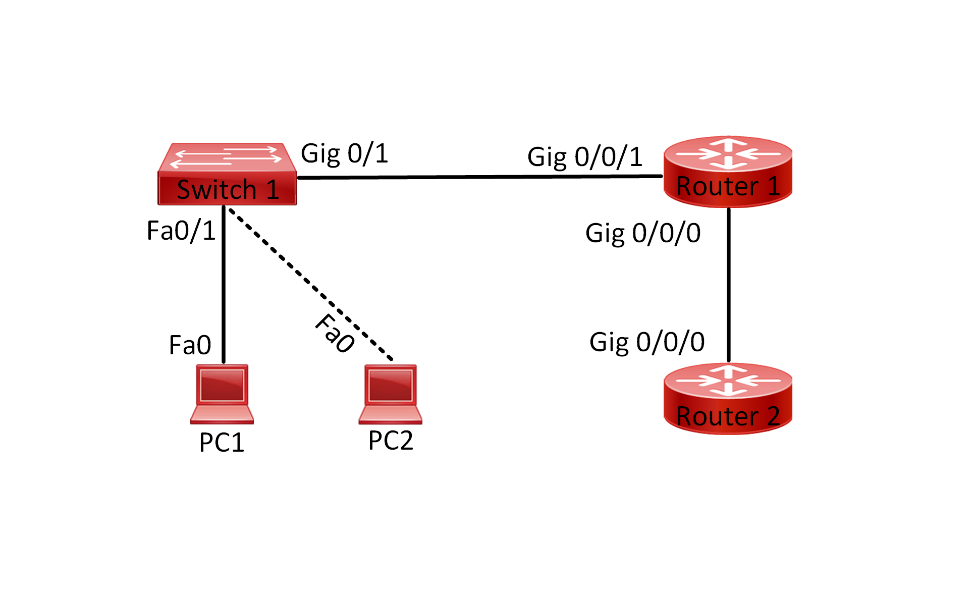
The objective of this lab is to configure and verify IPv6 static addresses on a network consisting of two switches, two PCs, and one router. By manually assigning IPv6 addresses to the devices, we aim to establish connectivity between PC1 and PC2 via Router1.
Lab Topology:

Equipment Required:
- 1x Cisco Router
- 2x Cisco Switches (2960)
- 2x PCs with ethernet interface
- Console Cable
- Ethernet Cable
- Computer with Terminal emulation software e.g. PuTTY
IPv6 Address Table:
| Device Name | Interface ID | IPv6 Address |
| Router 1 | GigabitEthernet0/0/0 | 2001:db8:2024:1::1/64 |
| Router 1 | GigabitEthernet0/0/1 | 2001:db8:2024:2::1/64 |
| PC 1 | Fa0 | 2001:db8:2024:1::254/64 |
| PC 2 | Fa0 | 2001:db8:2024:2::254/64 |
List of Command Summary:
| Command | Command Description |
| enable | enters privileged EXEC mode. |
| configure terminal | enters global configuration mode from privileged EXEC mode. |
| hostname [hostname] | Assign a device name to router. |
| interface [type number] | Change from global configuration mode to interface configuration mode. |
| ipv6 unicast-routing | used to enable IPv6 unicast routing on a Cisco router or switch. When enabled, the device will forward IPv6 packets between different networks or subnets, allowing for communication between devices on different IPv6 subnets. This command essentially enables the router or switch to act as an IPv6 router, facilitating the routing of IPv6 packets across the network. |
| ipv6 enable | used to enable IPv6 processing on an interface in Cisco IOS. When this command is applied to an interface, it enables IPv6 functionality on that interface, allowing the interface to send and receive IPv6 packets. |
| ipv6 address [ipv6 address] | Configure a static IPv6 address on an interface |
| show ipv6 interface [interface-id] | Display IPv6 configuration details for an interface. |
| no shutdown | enables an interface. |
| ping ipv6 [ipv6 address] | used to send an IPv6 ping message to a specific IPv6 address. This command is similar to the IPv4 ping command but is used for IPv6 addresses. By specifying the IPv6 address, the device attempts to ping another device with that specific IPv6 address to check for connectivity. |
| show running-config | save the running configuration to the startup-configuration file. |
| show running-config interface [interface-id] | display the current running configuration of a specific interface on a Cisco device. This command provides detailed information about the configuration settings applied to the specified interface, including IP addresses, VLAN assignments, interface status, and any configured parameters such as speed, duplex mode, or access control lists (ACLs) |
| show ipv6 interface brief | used to display a brief summary of IPv6 information for all interfaces on a device. This command provides a concise overview of each interface’s IPv6 configuration, including the interface name, IPv6 address, status, and protocol status. It is helpful for quickly assessing the IPv6 configuration of a device’s interfaces. |
| end | exit configuration mode |
| exit | exits one level in the menu structure command |
Lab Task:
- Connect the devices according to the provided topology.
- Connect to the CLI of the router, switches and enable privileged EXEC mode and go to configuration mode. Configure the appropriate hostname on each device as per topology shown above.
- Configure IPv6 addresses on PC1 and PC2.
- Verify that PC1 and PC2 have the correct IPv6 address.
- Configure unicast routing on Router1.
- Configure IPv6 addresses on Router1 interfaces.
- Verify each physical interface connected to the switches have the correct IPv6, once confirmed save the configuration.
- Verify IPv6 connectivity between PC1 and Router1.
- Verify IPv6 connectivity between PC2 and Router1.
- Verify IPv6 connectivity between PC1 and PC2.
Configuration Steps:
1. Connect Lab Devices: Connect the devices according to the provided topology. Ensure that Switch1 and Switch2 are both connected to Router1 and PC1 is connected to Switch1 and PC2 is connected to Switch2.
2. Change the name of the router and on both switches according to the topology:
On Switch 1:
switch> enable
switch# configure terminal
switch(config)# hostname Switch1
On Switch2:
switch> enable
switch# configure terminal
switch(config)# hostname Switch2
On Router 1:
Router> enable
Router# configure terminal
Router(config)# hostname Router1
3. On Packet Tracer, click on the PC1/PC2 icon and then go to Desktop and manually configure the IPv6 as per table shown above. See example below:
On PC1:

On PC2:

4. Verify the configurations on bot PCs, you can execute this command “ipconfig” from the CLI of each PC example shown below:
On PC1:

On PC2:

5. Configure ipv6 unicast routing on Router1:
Router1(config)#ipv6 unicast-routing
6. Configure static IPv6 address on both interfaces:
On interface gig 0/0/0:
Router1(config)#interface gigabitEthernet 0/0/0
Router1(config-if)#ipv6 enable
Router1(config-if)#ipv6 address 2001:db8:2024:1::1/64
Router1(config-if)#no shutdown
Router1(config-if)#exit
On interface gig 0/0/1:
Router1(config)#interface gigabitEthernet 0/0/1
Router1(config-if)#ipv6 enable
Router1(config-if)#ipv6 address 2001:db8:2024:2::1/64
Router1(config-if)#no shutdown
Router1(config-if)#end
7. We would issue the following commands:
“show ipv6 interface brief”
These commands will not work on Packet Tracer:
“show running-config interface gig0/0/0”
“show running-config interface gig0/0/1”
8. Ping between PC1 and router1:

9. Ping between PC2 and router1:

10. Ping between PC1 and PC2:

Don’t forget to save the running configuration on the device.
Important Note:
Upon configuring an IPv6 global unicast address, the interface is automatically activated for IPv6 utilization, and an IPv6 link-local address is allocated to it using the EUI-64 method.
The link-local address is functional solely for communications within the corresponding network segment, commonly known as a broadcast domain, to which the router interface is linked.
You have the option to bypass the EUI-64 method by explicitly assigning a link-local address using the link-local keyword. In this scenario, the address must fall within the appropriate range of FE80::/10; otherwise, an error message will be displayed.
Conclusion:
In this lab, we successfully configured and verified static IPv6 addresses on devices in a network. By understanding how to assign static IPv6 addresses and verify connectivity, we have gained valuable insights into IPv6 addressing and communication, and demonstrated the basic setup of IPv6 communication in a network environment.
Packet Tracer Lab (Pre/Post configuration):
Download the file below and open the word document to access the Packet Tracer labs.


