Lab 001 IPv4 Addressing and Subnetting Configuration with Two Switches
Watch Full Demo on YouTube:
Lab Objective:
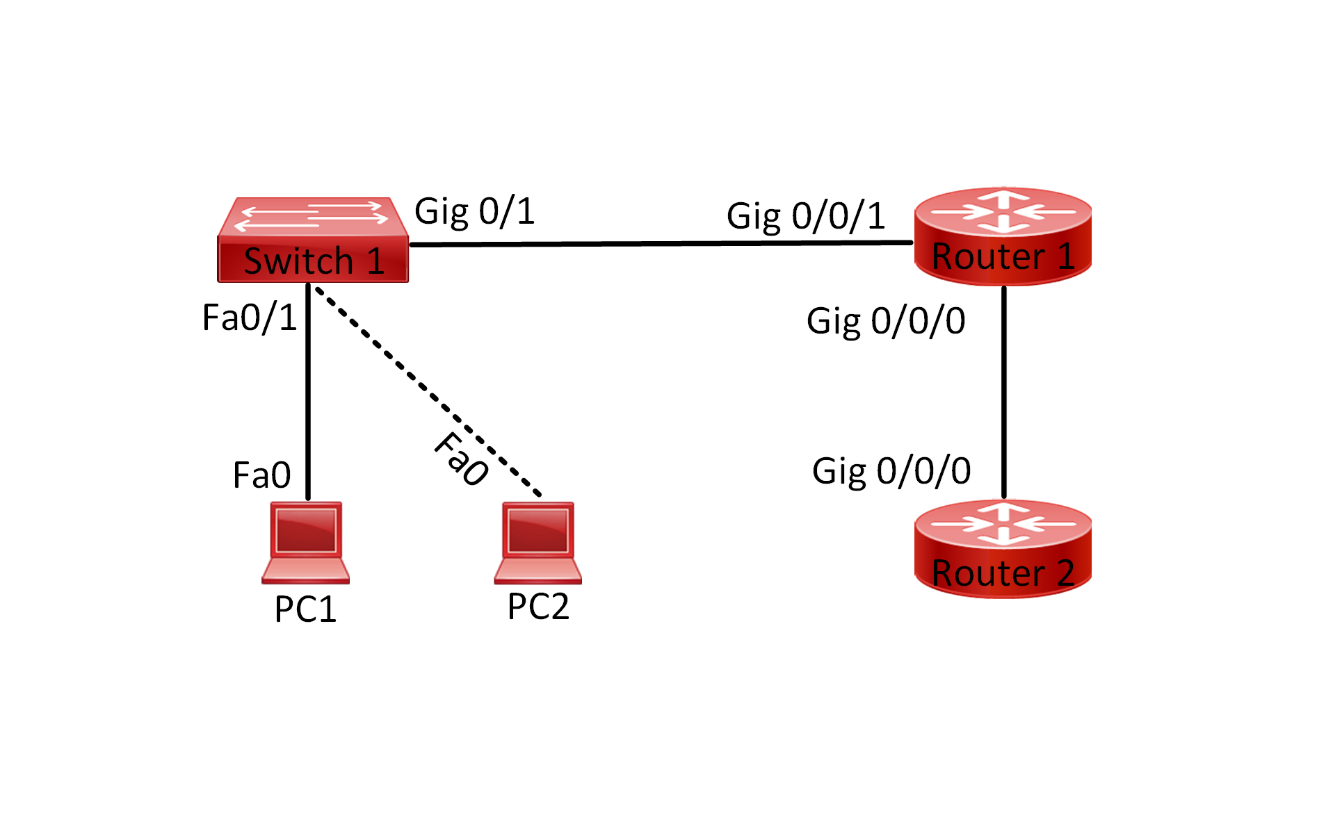
This lab focuses on configuring and verifying IPv4 addressing and subnetting in a network setup consisting of one router, two switches, and two PCs. Specifically, I will guide you through the basic steps of IPv4 address configuration and subnetting on a Cisco Router 4300 device.
To enable communication, each router interface that connects to a network must be assigned an IPv4 or IPv6 address. Furthermore, it is crucial that every IP address on the router belongs to a different subnet, ensuring proper network segmentation and routing.
On the other hand, each PC connected to a switch will operate within its own subnet. The default gateway for each PC will be configured as the IP address of the corresponding router interface, facilitating communication between devices across the network.
By the end of this lab, you will have a solid understanding of how to configure IPv4 addresses and subnetting to establish seamless connectivity within this network environment.
Lab Topology:

Equipment Required:
- Cisco Router
- 2x Cisco Switches (2960)
- 2x PCs with ethernet interface
- Console Cable
- Ethernet Cable
- Computer with Terminal emulation software e.g. PuTTY
IPv4 Address Table:
| Device Name | Interface ID | IPv4 Address | Subnet Mask |
| Router_Gateway | Gig0/0/0 | 192.168.0.1 | 255.255.255.0 |
| Router_Gateway | Gig0/0/0 | 192.168.1.1 | 255.255.255.0 |
| PC1 | Fa0 | 192.168.1.100 | 255.255.255.0 |
| PC0 | Fa0 | 192.168.0.100 | 255.255.255.0 |
List of Command Summary:
| Command | Command Description |
| enable | enters privileged EXEC mode |
| configure terminal | enters global configuration mode from privileged EXEC mode |
| hostname [hostname] | Assign a device name to router |
| interface [type number] | Change from global configuration mode to interface configuration mode |
| ip address [ipv4-address] [subnetmask] | assign an IPv4 address to an interface |
| no shutdown | enables an interface |
| interface range [type number]-[type number] | This is used to enter interface configuration mode for a range of Ethernet interfaces |
| switch mode access | set the operational mode of an interface to access mode |
| switch access vlan [vlan-ID] | assigns a specific VLAN to an access port |
| ping [ipv4-address] | Sends an ICMP (Internet Control Message Protocol) echo request to the specified address |
| show running-config | save the running configuration to the startup-configuration file |
| show ip interface brief | display a summary of all IPv4 addresses configured on the Router’s interfaces |
| show vlan brief | displays a brief summary of the VLAN configuration on the switch including the VLAN ID, VLAN name, and port membership |
| end | exit configuration mode |
| exit | exits one level in the menu structure command |
| clear arp | deletes all entries from the ARP table |
Lab Task:
- Configure Router with a hostname of “Router_Gateway”. Enable both interfaces Gig0/0/0 and Gig0/0/1
- Configure each interface with the appropriate IPv4 address mentioned above
- Configure PC1 and PC0 with the appropriate IPv4 address mentioned above
- Verify your configuration by using “show ip interface brief”, “show running-configuration” and “ping” commands. The ping should be successful
- Save Configuration
Configuration Steps:
- Physical Connection:
- Connect your computer to the console port of the router using the console cable. Connect Switch 1 to one Ethernet interface on the router using an Ethernet cable. Connect PC1 to Switch 1 using an Ethernet cable.
- Terminal Access:
- Open a terminal emulation program (e.g., PuTTY) on your computer.
- Configure the terminal emulator to connect to the console port of the router using the appropriate COM port and baud rate settings.
- Router Configuration:
- Access the router’s console through the terminal emulator. Enter privileged EXEC mode by typing enable and providing the enable password if prompted. Enter global configuration mode by typing configure terminal. Configure IP addresses on each router interface connected to the switches:
- interface GigabitEthernet0/0/0ip address 192.168.0.1 255.255.255.0no shutdown interface GigabitEthernet0/0/1ip address 192.168.1.1 255.255.255.0no shutdown
- Exit configuration mode by typing end.
- Access the router’s console through the terminal emulator. Enter privileged EXEC mode by typing enable and providing the enable password if prompted. Enter global configuration mode by typing configure terminal. Configure IP addresses on each router interface connected to the switches:
- PC Configuration:
- Configure PC1’s network settings to use the following IPv4 address: 192.168.1.100, subnet mask 255.255.255.0, default gateway 192.168.1.1.
- Similarly, configure PC0’s network settings to use IP address 192.168.0.100, subnet mask 255.255.255.0, default gateway 192.168.0.1.
- Verification:
- Verify the configured IP addresses and interfaces on the router, switches, and PCs using appropriate show or network configuration commands.
- Test connectivity between PC1, PC2, and the router by pinging each other’s IP addresses.
- Subnetting (Optional):
- Practice subnetting by dividing the provided IP address ranges into smaller subnets and assigning IP addresses to hosts within each subnet. Configure additional IP addresses and subnets on the router, switches, and PCs interfaces accordingly.
Don’t forget to save the running configuration on the device.
Conclusion:
In this lab, you have successfully configured and verified IPv4 addressing and subnetting on a network with one router, two switches, and two PCs. You have learned how to assign IP addresses to router, switch, and PC interfaces, verify connectivity, and practice subnetting to create smaller subnets within a network range.
Packet Tracer Lab (Pre/Post configuration):
Download the file below and open the word document to access the Packet Tracer labs.


