CCNA 200-301 Chapter 1 Network Fundamentals Lab 011 Troubleshoot LAN Issues – Basic Level
Watch Full Demo on YouTube:
Lab Objective:
The objective of this lab is to familiarize participants with common interface error messages, their meanings, and troubleshooting steps to resolve them.
We will cover the following:
1- duplex mismatch issues
2- speed mismatch
3- VLAN issues
4- Trunk issues.
Lab Topology:

Equipment Required:
- 2x Cisco switch (e.g., Cisco Catalyst series)
- 4x PCs or laptops with Ethernet ports
- Console Cable
- Ethernet Cable for connections between devices
- Computer with Terminal emulation software e.g. PuTTY
IPv4 Address Table:
A. Switch VLAN Table:
| Device Name | Interface ID | Interface Mode | Allowed VLANs |
| Switch1 | GigabitEthernet0/1 | Trunk | 100, 200 |
| Switch1 | Fa0/1 | Access | 100 |
| Switch1 | Fa0/2 | Access | 200 |
| Switch2 | GigabitEthernet0/1 | Trunk | 100, 200 |
| Switch2 | Fa0/1 | Access | 100 |
| Switch2 | Fa0/2 | Access | 200 |
B. Hosts IP Address Table:
| Device Name | Interface ID | IPv4 Address | Subnet-Mask | Default Gateway | VLAN |
| PC1 | Fa0 | 192.168.100.1 | 255.255.255.0 | N/A | 100 |
| PC2 | Fa0 | 192.168.200.1 | 255.255.255.0 | N/A | 200 |
| PC3 | Fa0 | 192.168.100.2 | 255.255.255.0 | N/A | 100 |
| PC4 | Fa0 | 192.168.200.2 | 255.255.255.0 | N/A | 200 |
List of Command Summary:
| Command | Command Description |
| enable | enters privileged EXEC mode. |
| configure terminal | enters global configuration mode from privileged EXEC mode. |
| hostname [hostname] | assign a device name to router. |
| switchport mode trunk | is used to configure an interface on a Cisco switch to operate in trunk mode. In trunk mode, the interface is capable of carrying traffic for multiple VLANs simultaneously. This command allows the interface to send and receive traffic with VLAN tags, enabling it to interconnect switches or routers and carry traffic for multiple VLANs across a single link. |
| switchport trunk allowed vlan ID | is used to specify which VLANs are allowed to traverse a trunk port on a Cisco switch. By default, all VLANs are allowed on a trunk port. However, this command can be used to restrict the VLANs that are permitted to pass through the trunk link. You can specify individual VLAN IDs or specify a range of VLAN IDs that are permitted on the trunk port. |
| show interfaces [interface-ID] switchport | is used to display detailed information about the switchport configuration of a specific interface on a Cisco switch. It provides information such as the administrative and operational mode of the switchport, the VLAN membership of the switchport, trunking status, allowed VLANs, native VLAN, and other relevant details related to the switchport configuration. |
| show interfaces trunk | displays information about trunk interfaces and their associated VLANs. It provides details about which interfaces are configured as trunk links, the encapsulation type (such as dot1Q), the operational status of the trunk, the allowed VLANs on the trunk, and the native VLAN. This command is useful for verifying trunk configurations and troubleshooting trunking issues on Cisco switches. |
| vlan [vlan-id] | used to create a new VLAN with the specified VLAN ID. This command allows network administrators to segment the network into multiple virtual LANs (VLANs) for better traffic management and security. By assigning devices to different VLANs based on their network requirements, administrators can control broadcast domains, enforce security policies, and optimize network performance. |
| switchport mode access | used on Cisco switches to configure an interface as an access port. Access ports are used to connect end devices, such as computers or printers, to the switch. When configured as an access port, the switch treats all incoming frames on that interface as belonging to the VLAN assigned to the port. This command disables dynamic trunking protocol (DTP) negotiation on the interface, ensuring that it operates only as an access port and does not participate in VLAN trunking. |
| switchport access vlan [VLAN-ID] | used on Cisco switches to assign a specific VLAN to an access port. This command is typically used in conjunction with the “switchport mode access” command to configure an interface as an access port and specify the VLAN to which it belongs. By assigning a VLAN to an access port, the switch ensures that all incoming traffic on that port is tagged with the specified VLAN ID. This allows the switch to segregate traffic from different VLANs and control broadcast and multicast traffic within each VLAN. |
| show vlan brief | used on Cisco switches to display a summary of VLAN information. When you enter this command in the CLI interface of a Cisco switch, it provides a concise overview of the VLAN configuration on the switch. This includes details such as the VLAN ID, name, and interface membership status. The output of this command is often used to quickly verify the VLAN configuration and interface assignments on the switch. |
| ipconfig /all | used in Windows operating systems to display detailed information about all network interfaces and their configurations. |
| no shutdown | enables an interface. |
| show running-config | save the running configuration to the startup-configuration file. |
| copy running-config startup-config | used to save the currently running configuration (stored in the RAM) to the startup configuration (stored in the NVRAM) |
| Duplex {auto|full|half} | The “duplex” command in Cisco IOS is used to manually set the duplex mode for an interface. Here’s the breakdown of each option: “auto”: This setting allows the interface to automatically negotiate the duplex mode with the connected device. The interface will attempt to determine the best duplex mode based on the capabilities of the connected device. “full”: This setting forces the interface to operate in full-duplex mode, allowing for simultaneous transmission and reception of data. This mode is typically used when the connected device also supports full-duplex communication. “half”: This setting forces the interface to operate in half-duplex mode, where data can only be transmitted or received at any given time, but not simultaneously. This mode is less common and generally used when connecting to legacy devices that do not support full-duplex communication. |
| Speed {10|100|auto} | The “speed” command in Cisco IOS is used to manually set the speed for an interface. Here’s the breakdown of each option: “10”: This setting forces the interface to operate at a speed of 10 Mbps (megabits per second). “100”: This setting forces the interface to operate at a speed of 100 Mbps (megabits per second). “auto”: This setting allows the interface to automatically negotiate the speed with the connected device. The interface will attempt to determine the best speed based on the capabilities of the connected device and the current network conditions. These options are typically used to ensure that the interface operates at the desired speed based on the requirements of the network and the capabilities of the connected devices. |
| end | exit configuration mode. |
| exit | exits one level in the menu structure command. |
Lab Task:
- Investigate as to why the link between PC1 and Switch1 is DOWN and fix the issue
- Troubleshoot the link between PC4 and Switch2 and fix the issue accordingly
- Initiate a ping from PC1 to PC3, is the ping successful? Is there connectivity between PC2 and PC4
- Now troubleshoot and investigate why PC1 is unable to ping PC3 and PC2 to PC4. Find where the problem and fix the issue accordingly.
- Re-test the ping between PC1 and PC3, also ping between PC2 and PC4.
- If the ping is successful then go ahead and save the configuration.
Troubleshooting Scenarios:
- Scenario 1: Interface showing input errors due to duplex mismatch.
- Scenario 2: Interface experiencing CRC errors due to cable issues.
- Scenario 3: Interface reporting runts or giants errors caused by frame size mismatch.
- Scenario 4: Interface showing output errors due to congestion or buffer overflow.
Lab Solution:
1. To investigate why the link between PC1 and Switch1 is down we need to check the following:
a. Check physical interface on both sides:
Switch1: issue this command “show ip interface brief”
We can see the interface is down/down which means that Layer1 is not working.

We also need to issue this command “show interface status” as this will give you information about the speed, the type of physical connection, the VLAN ID, the status, and the duplex setting.

From the output above we can be certain that the speed on the interface is operating at a 10 mbps. The Duplex setting is auto and it is part of VLAN 100.
In addition, we can issue this command “show interfaces fa0/1” to get statistics about the physical interface.

We can read from the output above that the duplex setting is set to half-duplex. The current speed is 10Mb/s and there are no CRC issues or packet drops.
Finally, we can check the configuration on the physical interface by issuing this command “show running-config”:

We can see that the interface is manually configured with 10 Mbps, the interface is part of VLAN 100 and is operating as in Access mode
On PC1: we go to Config -> INTERFACE ->FastEthernet0

We can read from the above that the interface is using 100Mbps and the duplex setting is set to Full Duplex.
Now we conclude that we need to sort out the speed mismatch and the duplex setting.
We can do this by issuing the following commands on Switch1:
Switch1#configure terminal
Switch1(config)#interface FastEthernet0/1
Switch1(config-if)#no speed 10
Switch1(config-if)#speed 100
Switch1(config-if)#duplex full
Now we should see the interface operate as expected
2. To troubleshoot the link between PC4 and Switch2 we need to repeat the same steps mentioned above. We can see that the duplex setting on interface Fa0/2 is set to Half-Duplex where as PC4’s FastEthernet0 is set to Full-Duplex, to fix this issue we can issue this command under interface fa0/2 on Switch2:
Switch2#configure terminal
Switch2(config)#interface fastEthernet 0/2
Switch2(config-if)#duplex full
The interface should come up and operate as expected.
3. Both pings fail as shown below:


4. To troubleshoot and investigate why PC1 is unable to ping PC3 and PC2 unable to ping PC4 we will need to check the following:
a. Check VLAN settings if applicable
b. Check Trunk mode
c. Check VLANs that are allowed via the Trunk
d. Check the interface between Switch1 and Switch2
e. Check STP type and check if the port is in the forwarding state
f. Check Syslog messages to look for hardware, software or configuration issues.
1) Check VLAN exists on both Switches:
On Switch1: We issue this command “show vlan brief”

We can see from the output above that Fa0/1 and Fa0/2 part of the correct VLAN, and both 100,200 VLANs exist on Switch1.
On Switch2: We issue this command “show vlan brief”

From the output above we can see that Fa0/1 is part of VLAN 10 which is incorrect, and VLAN 100 does not exist.
To fix this issue we can issue the following commands on Switch2:
Switch2#configure terminal
Switch2(config)#vlan 100
Switch2(config-vlan)#inter fa 0/1
Switch2(config-if)#switchport access vlan 100
Next we need to check status on each interface that interconnects Switch1 and Switch2.
On Switch1:

We can see that Gig0/1 is connected and part of VLAN 1 which is the native VLAN. We know this interface should operate in Trunk mode to carry multiple VLANs across. So this need to be fixed.
On Switch2:

The above output shows that Gig0/1 is connected, and is operating in Trunk mode which is what expected.
So the issue on that link at this moment is because one side of the link is set to Access mode and the other side is set to Trunk mode. This will cause connectivity issues between Switch1 and Switch2. To fix this issue we need to issue the following commands on Switch1:
Switch1#configure terminal
Switch1(config)#interface gigabitEthernet 0/1
Switch1(config-if)#switchport mode trunk
3. Now we can check connectivity again between PC1 and PC3 and PC2 to PC4:
PC1 was able to ping PC3 however PC2 couldn’t reach PC4 so we need to carry on further troubleshooting.
4. On each Switch we need to check the switchport, so issue this command “show interface gig0/1 switchport” on both Switches:
On Switch1:

We can see from the output above, that the Trunk is allowing all VLANs and it is configured as a Trunk
Another command we could use is “show interface trunk”

On Switch2:

Another command we could use is “show interface trunk”:
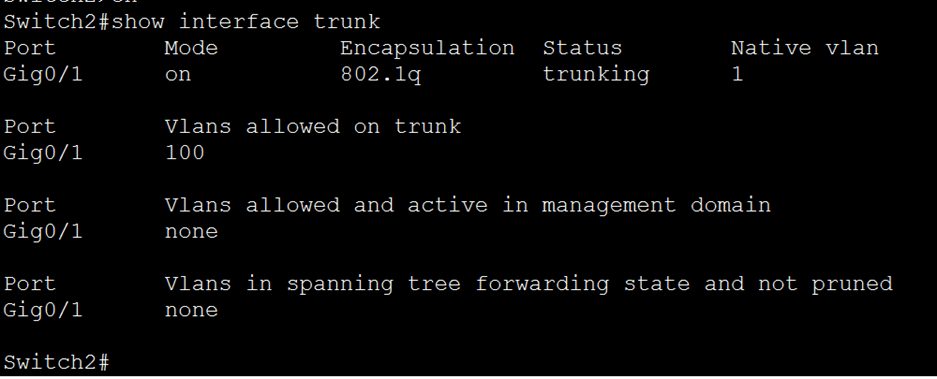
On Switch2 we can see that the only VLAN allowed is VLAN 100 Hence why PC2 couldn’t ping PC4 since they are both part of VLAN 200.
To fix this issue we need to issue the commands below on Switch2:
Switch2#configure terminal
Switch1(config)#interface gigabitEthernet 0/1
Switch2(config-if)#switchport trunk allowed vlan add 200
Now we should be able to ping PC2 and PC4
12. Save the configuration by issuing either “wr” or “copy running-config startup-config” command on all Cisco devices.
Troubleshooting:
- If ping fails, double-check IP addressing, subnet masks, default gateways, switch and router configurations.
- Ensure that routing is correctly configured to allow traffic between subnets.
- Ensure Each PC is in the correct VLAN and that each VLAN is allowed throughout the trunk link between Switch1 and Router1.
Note:
To investigate any issues within LAN, you will need to do the following:
- Physical Connections Check:
- Ensure that the Ethernet cable is securely connected to both the PC’s network interface card (NIC) and the switch port.
- Check for any physical damage to the cable or the connector pins.
- Link Status Check:
- Verify the link status on the switch port and the PC’s network interface.
- Look for LED indicators on both devices to confirm link connectivity. A solid or blinking LED usually indicates an active link.
- Network Interface Configuration Check:
- Confirm that the PC’s network interface is configured correctly, including IP address, subnet mask, gateway, and DNS settings.
- Check for any misconfigurations or conflicts with other devices on the network.
- Switch Port Configuration Check:
- Ensure that the switch port is configured correctly, especially if it’s a managed switch.
- Check the switch port’s configuration for VLAN membership, speed, duplex settings, and any security features (e.g., port security, VLAN access control lists).
- VLAN Membership Check (if applicable):
- Verify that both the PC and the switch port are members of the same VLAN, especially in environments with VLAN segmentation.
- Duplex and Speed Mismatch Check:
- Ensure that the speed and duplex settings on both the PC’s network interface and the switch port match. Mismatches can lead to performance issues or connectivity problems.
- Consider setting the speed and duplex settings to “auto” on both ends for automatic negotiation.
- Hardware Testing:
- If possible, try connecting the PC to a different switch port or using a different Ethernet cable to rule out hardware issues.
- Test the PC’s network interface by connecting it to a different device or network to determine if the problem persists.
- Ping Test:
- Use the “ping” command from the PC’s command prompt to test connectivity to other devices on the same subnet or to the switch’s management IP address.
- If the ping fails, troubleshoot any network configuration issues or connectivity problems identified during the previous steps.
- Packet Capture (if necessary):
- If the issue persists and the cause is not apparent, consider using packet capture tools like Wireshark to analyze network traffic and identify any anomalies or errors.
- Documentation and Escalation:
- Document all troubleshooting steps taken, including any changes made to network configurations.
- If unable to resolve the issue, escalate to higher-level support personnel or consult vendor documentation for further assistance.
Conclusion:
By the end of this lab, participants should be able to recognize common interface error messages, understand their causes, and take appropriate troubleshooting steps to resolve them, ensuring optimal network performance.
Packet Tracer Lab (Pre/Post configuration):
Download the file below and open the word document to access the Packet Tracer labs.